Radio Telescope
The RF over Fiber (RFoF) solution for Radio telescopes is designed for radio astronomy observatories. It is customized to meet the stringent stability and accuracy which are essential to achieve precise timing and signal transmission between antenna sites and the radio telescope processing centers. Timing precision is important to enable processing signals of Very Long Baseline Array (VLBA) observatories from around the world to generate a composite high-resolution radio image of distant celestial objects many light-years away. The RFOptic bidirectional WDM system provides timing stability well under 1ps RMS over 24 hours. It has been successfully deployed around the world for the last 8 years demonstrating excellent and reliable performance. The system is comprised of indoor and outdoor units and is Ethernet compatible using a webserver interface for monitoring and control.
Why use RF over Fiber and not coax?
At radio telescope astronomy sites, one or more massive dish antenna located at a distance from the control building. The antenna requires timing reference signal for precise synchronization as well as several up and downlink wideband signals. The RFoF WDM bidirectional solution transmits these signals with ease providing a flat wideband transmission response featuring low loss and stable performance. Timing precision and stability is key to the synchronization of signals of VLBA observatories, therefore, the RFoF links are designed for extreme stability over time and temperature. Due to its insertion loss profile over frequency, coaxial cables are unable to handle the required bandwidth reaching as high as 18GHz and the distances to the antenna site of 800m or more.
Key characteristics
Generally, radio telescope observatories use RF over Fiber WDM technology to connect their huge dish antennas with the control room without digitization which limits the bandwidth and dynamic range of the signal and adds digitization artifacts such as aliasing. Scientists prefer to use the entire signal bandwidth demanding wideband, low noise, high linearity and above all a stable connection for precise timing.
Main Applications
In most cases, signal frequencies from 0.1GHz to 18GHz or from 1MHz to 6GHz must be transmitted along with additional timing and reference signals. In some cases, several wideband signals are transmitted in the uplink for synchronization. A typical site contains two Antenna sites each of which might include multiple antennas. RFOptic offers customized enclosures which are produced according to the requirements of each observatory. Our RFoF system for radio telescopes has been installed and is operational at various Radio Astronomy Observatories dedicated to scientific research around the world including the Very Long Baseline Interferometry Global Observing System (VGOS) radio telescope in Sweden, Germany, South Africa, and China.
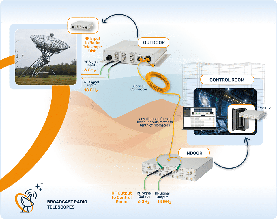
System Configuration Example
RFOptic’s multilink RF over Fiber solution was customized to meet the specifications of one of the largest astronomical observatories. It comprises RFoF Transmit and RFoF Receive modules housed in outdoor and/or indoor enclosures. Each enclosure can house up to 4 RFoF Tx or Rx modules or more. The outdoor enclosure is populated with 2 Tx of 18GHz and 2Tx of 6GHz. The indoor rack mountable 1U removable chassis includes 2Rx of 18GHz and 2Rx 6GHz modules. An IFL module (interfacility link) is used for remote management when network connection near the antenna is not possible.
System Configuration (Example)
RFOptic’s multi-link unidirectional RF over Fiber solution was customized to meet the specifications of one of the largest astronomical observatories. It comprises of an RFoF Transmit and Receive modules housed in outdoor and/or indoor enclosures. An outdoor enclosure is populated with two 18GHz RFoF Tx modules as well as two 6GHz Tx modules. The indoor rack mountable 1U removable chassis is installed with two 18GHz Rx modules and two 6GHz Rx modules. An IFL module (Ethernet over fiber interfacility link) is added for remote management where a network connection near the antenna site is not available. Additional RFoF and TTLoF links could be added to achieve a comprehensive solution for each particular antenna site.
Monitoring & Control
RFOptic multilink products and subsystems may include a remote Management and Control (M&C) option. These products can be managed and controlled over the Internet Protocol (IP). The M&C supports HTML Web Server), REST, and SNMP V2c protocols.
Conclusion
RF over Fiber is an excellent solution for remote antennas for radio telescope observatories since the solution provides wide bandwidth, low noise figure, and good gain flatness and stable timing links together with the remote management and control system. The above application of RFOptic is the proven solution that can be delivered within a short time upon request.
Contact Us