RF over Fiber for 5G Testing
The growing demand for 5G and 6G RF over Fiber testing is driven by the need for higher frequency and bandwidth capabilities, long-distance performance, and remote management, featuring high dynamic range. Such systems are designed for base stations and interoperability test sites, addressing remote management and configuration that allow test automation. RFOptic has developed advanced RFoF systems that focus on dynamic range performance and are optimized to address critical criteria including EVM and ACLR over the ever-widening channel bandwidths. RFOptic’s 5G and 6G solutions are delivered in a 2U high-density platform, capable of housing up to 20 bidirectional terminals or up to 40 transmitters or receivers in each enclosure. This compact design is modular using 5 drawers too allow for flexible configuration supporting common or separate RF up and down link ports as well as single or multiplexed fiber ports. The Remote management interface provides full automation API. It auto-configures itself to the hardware, enhancing operational efficiency and convenience.
WHY RFoF INSTEAD OF COAX FOR BASE STATION TESTING?
Coaxial cable infrastructure and RF switches were standard until the advent of 5G frequency bands and communication protocols. However, coaxial cables severely limit distance and performance, making RF over Fiber the preferred solution for test facility connections between radio base stations and Customer Premises Equipment (CPE).
With the rapid evolution of the RF high-frequency market due to 5G and 6G advancements, customers seek integrated, end-to-end solutions. RF over Fiber offers significant benefits, including handling bandwidths up to 67GHz while minimizing crosstalk and maintaining high spurious-free dynamic range (SFDR).
KEY CHARACTERISTICS FOR 5G & 6G RF TESTING
RFOptic bi-directional RFoF system deliver RF performance that surpasses traditional coaxial cable interfaces for practical test environment distances. These solutions are specifically designed for the 5G and 6G cellular bands, covering a wide bandwidth range from 0.5 GHz to 6 GHz and higher, with options for narrower bandwidths of 2.5GHz, 3GHz, and 4GHz as needed.
Our high-density (HD) multi-channel mainframe offers a compact and flexible solution for RFoF signal distribution in 5G and 6G applications. This 2U, 19” rack-mountable mainframe accommodates up to five hot-swappable RFoF drawers, each containing eight RFoF units. This modular design not only maximizes link density but also simplifies maintenance and configuration, allowing for easy adaptation as additional RFoF channels are required.
The HD mainframe features a redundant power supply, forced-air thermal management, and remote management services, enabling comprehensive monitoring and control of the RFoF system and its components through HTML, REST, and SNMP interfaces. For applications needing fewer RFoF modules, a 1U, 19” configuration is also available, both enclosures support unidirectional or bi-directional full-duplex setups.
Our management system is accessible through the RFOptic HTML/SNMP interfaces or integrated using an API into larger NOC systems. This capability significantly reduces operational expenditures (OPEX) while enhancing system efficiency and reliability.
FREQUENCY RANGE & RF COVERAGE
In most cases, RF over Fiber systems for 5G applications must cover frequencies from 0.5 GHz to 4 GHz or from 0.5 GHz to 6 GHz. Recently, there has been a growing demand for coverage extending from 0.5 GHz to 7.1 GHz, with an emphasis on enhanced dynamic range which is manifested through Error Vector Magnitude (EVM) and Adjacent Channel Leakage Ratio (ACLR) for wide channel bandwidths increasing from 50MHz to 100MHz and even 200MHz. To meet these requirements, RFOptic recommends its innovative RFoF ULTRA 10GHz solution. Future 6G cellular systems are allocated even higher frequencies which are covered by the RFoF ULTRA 15GHz or 18GHz solutions. We also anticipate that future systems will need to accommodate millimeter-wave frequencies as the demand for higher bandwidth continues to rise.
BASE STATION APPLICATION & SYSTEM ARCHITECTURE
Our RF over Fiber system for 5G applications has been installed and is operational at various locations around the globe, including state-sponsored facilities focused on advanced telecommunications research. This solution utilizes efficient RF over Fiber technology to establish connectivity between the tested Customer Premises Equipment (CPE) and the radio base station.
The entire system is housed indoors, featuring a 2U high-density 19″ enclosure(s) that accommodate(s) multiple transmitters and receivers. Utilizing a third-party optical switch, the test setup using RFoF connectivity ensures optimal signal management and routing. This architecture enables the 5G test system to operate seamlessly over the test frequencies and channel bandwidths while delivering excellent dynamic range, Adjacent Channel Leakage Ratio (ACLR), Error Vector Magnitude (EVM), temperature stability, good noise figure, and linearity. Moreover, all RFoF parameters can be monitored and controlled remotely and centrally, providing automated configuration, increasing test equipment usage rate, and allowing for superior performance in high-demand applications.
RFOptic has provided such RFoF systems to a number of base station vendors, which have been successfully deployed in testing facilities.
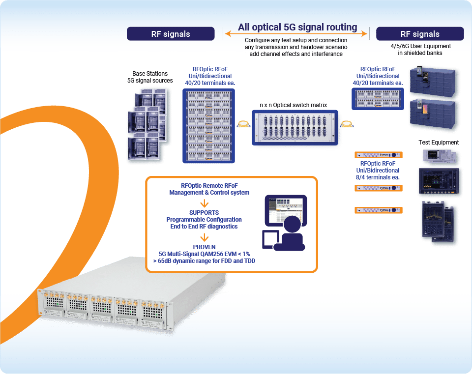
SYSTEM CONFIGURATION (EXAMPLE)
5G cellular base station handover and interoperability tests require reconfigurable connection of base stations, test equipment and User Equipment (UE). RFOptic’s 2U high-density RFoF systems are designed to support both bi-directional and unidirectional topologies, accommodate a mix of unidirectional transmitters and receivers as well as bi-directional RFoF terminals operating up to 10 GHz in drawers. These RFoF mainframes are connected to the local area network (LAN) via an RJ-45 connector, offering for easy integration. Users can manage the system remotely through a dedicated IP address using REST API, enabling efficient monitoring and control. Each enclosure can hold up to five hot-swappable drawers, which are available with different RFoF configurations. The 2UHD systems are strategically installed near the test base stations, while the remote system is positioned close to the UE and test equipment. Using an optical switch matrix, any signal can be conditioned and routed to any piece of equipment. Since both routing and RFoF connectivity is all under remote management, the test facility can reconfigure itself electronically for different test scenarios in a very short time. This approach minimizes downtime for any test or other equipment and allows for unattended extensive test procedures.
REMOTE MONITORING AND CONTROL (M&C)
RFOptic multilink products and subsystems may include a remote Management and Control (M&C) option. These products can be managed and controlled over Internet Protocol (IP). The M&C supports HTML Web Server, REST API, and SNMP V2c protocols. The M&C system considers all connected products as modules or terminals, which can be either Rx or Tx, or subsystems such as an ODLs. The M&C interface treats each of these components independently. For each component, the M&C displays and avails access to all the associated status and control capabilities particular to the component under all the above interface protocols. The M&C system can be configured for specific modules or may be set up to reconfigure itself to accept any product dynamically. For more information, please review the M&C section on our website.
INSTALLATION CHECKLIST
Installation of the RFoF systems is straightforward, for example see the installation steps of the 2UHD:
- Carefully inspect the package for any signs of damage that may have occurred during transportation.
- Gently remove the 2U chassis from the packaging, ensuring no parts are disturbed or damaged.
- Slide out the five drawers from the 2U chassis to prepare for installation.
- Install the 2U chassis into the 19” rack-mount platform, ensuring there is adequate space and connectivity for power, internet, RF cables, and optical cables.
- Re-insert the five drawers into the chassis and proceed to connect the optical cables to the back panel, RF cables to the front panel, and the internet connection to the RJ-45 port on the back panel.
- Connect the power plug to the socket and power on the system.
- Verify that all five drawer green LEDs are lit, indicating proper system is fully functional.
- Once the system is fully operational, begin the network connection procedure to gain control of the system.
CONCLUSION: VALIDATING 5G/6G BASE STATIONS WITH RFoF
The RFoF technology has been proven to be a highly effective solution for replacing traditional coaxial cable infrastructure in base station testing environments. With its superior performance and the added benefit of remote Management and Control (M&C), which significantly helps reduce OPEX, RF over Fiber is an ideal choice for modern telecommunications applications.
RFOptic’s cutting-edge solutions support frequencies up to 7.1GHz and beyond, meeting the evolving demands of next-generation networks. Our systems’ robust capabilities, reliability, and cost-efficiency have earned RFOptic’s customers’ full satisfaction, making RFOptic a trusted partner in the industry. By choosing RF over Fiber, operators can optimize their network performance, simplify maintenance, and future-proof their infrastructure, all while reducing operational costs.
Contact Us