5G testing in a telecom provider’s lab for interoperability purpose
July 26, 2025
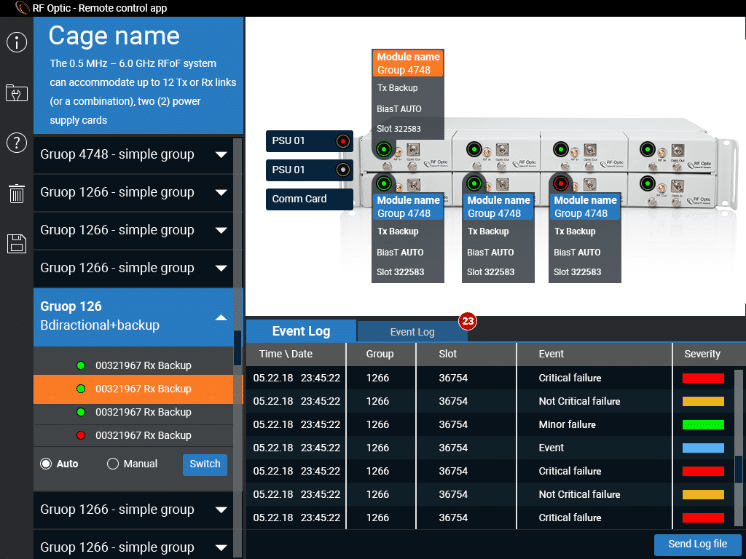
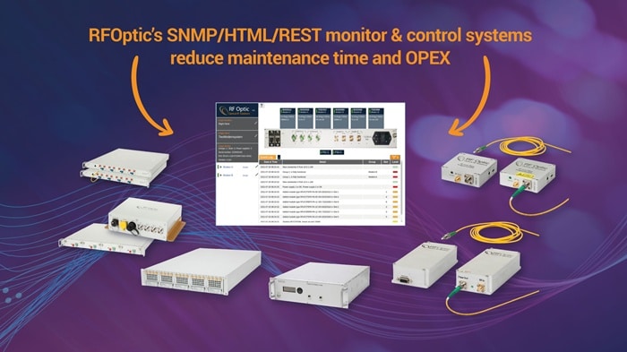
The increasing demand for 5G connectivity necessitates robust interoperability testing across diverse base station equipment within telecom laboratories. RFOptic's RF over Fiber (RFoF) solutions offer a superior approach to traditional coaxial infrastructure, enabling efficient and effective 5G testing. The challenge A leading telecommunications provider was looking for an RFoF solution to conduct 5G interoperability testing in its European labs. The...
Read more