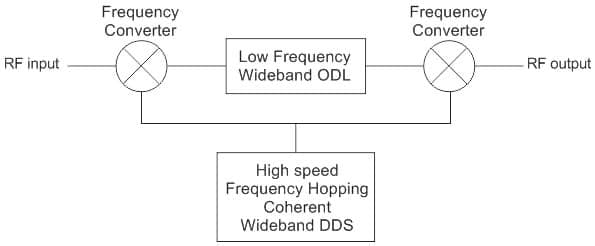
An Optical Delay Line system (ODL) incorporates high-performance lasers such as DFBs, optical modulators for high operation frequencies, and photodiodes. It can also incorporate other components such as optical dispersion compensators, optical switches, optical amplifiers and pre- and post RF amplifiers for exceptionally high performance. For various delays, the ODL optical system supports very high bandwidths of analog signals, high sensitivity with wide dynamic range.
The ODL method is so important, since it is the most accurate and reliable method for time domain measurement for delay times of a few nano seconds to hundreds of microseconds. In other words, an Optical Delay Line is a method of wave guide where the media is fiber with a fixed index of refraction and relative constant group delay variation.
There are various applications that can use ODL systems, such as radar range calibration, MTI (Moving Target Indication), clutter canceller, BIT, ground-based system test, radar warning receiver, jammers for EW systems, timing control, path delay simulation, and phase shift discriminator.
The Optical Delay line method is the most accurate and reliable method for time domain measurement for delay times of a few nano seconds to hundreds of microseconds. As mentioned above, an Optical Delay Line is a method of wave guide where the media is fiber with a fixed index of refraction and relative constant group delay variation. The main advantages of this method as compared to other methods are:
- Delay Length – Long achievable delay line due to the extremely low loss of the fiber (~0.25dB/Km), which is not achieved in any other methods. There are methods that can measure a range of picoseconds such as light reflection but do not cover the typical range of radars or EW systems. There are also methods for very long delay lines in the order of milliseconds, which are not accurate for practical lengths of delays. Therefore, the Optical Delay Line is the suitable method for length range from a few nano seconds to hundreds of microseconds. Moreover, utilizing switching or progressive system architectures, it is possible to include several different delays in the same system, which saves space, weight etc.
- Bandwidth – Optical Delay Line can support bandwidths from the MHz range to tenth of GHz. This allows for using the ODL in various applications which require high bandwidth, where other waveguide methods are limited in allowed bandwidth and applications. For example SAW is used for a bandwidth of a few tenths of kilohertz.
- Group Delay Variation – One of the most important issues for radar designers is that the delay will be equal in the entire bandwidth. Thanks to the fiber, the group delay is constant and very small compared to the delay length.
- Spurious – The spurious level of the Optical Delay Line is small, supporting Doppler shift measurements / applications, where the noises which are caused due to the circuit boards are cleaned by the system.
- Phase Noise – An important parameter in the performance of airborne radars is the phase noise of the radar’s carrier frequency. Low phase noise is important for an accurate long range detection of a target. Many phase noise testing sets utilize waveguide delay lines as part of the test circuit. Because of their size, weight, and signal attenuation, typical waveguide delay lines have length limitations. Replacing the waveguide with fiber optic delay line allows for a major reduction in size and weight, as well as an added ability to improve the sensitivity of the test set in measuring phase noise close to the radar’s carrier frequency. A laser diode with low Relative Intensity Noise (RIN) can provide at 0 delay length a phase noise less than -130 dBc (input of).
There are various applications that can use ODL systems, including:
- Radar range calibration; MTI (moving target indication); Clutter Canceller; BIT; Ground Based System Test; Radar Warning Receiver; Jammers for EW Systems; Timing Control; Path Delay Simulation; and Phase Shift Discriminator.
The main features support transmission of RF and Microwave analogue signals, covering:
- L band, S band, C band, X band, and Ku band for various applications.
- Supports width bandwidth analogue signals.
- Supports various delay lines ranging from a few ns up to hundreds of m
- High dynamic range.
- Excellent delay repeatability and phase linearity.
- Small Group Delay Variation.
- Easy operation – Manually or remotely management & control.
Main configurations:
- Fixed Delay Line System
The basic ODL system configuration consists of one Transceiver and one fixed Delay Line module that are integrated in one enclosure. ODL versions where the Transceiver and Delay Line units are separated into two modules are optional. The two modules option provides the flexibility to use one ODL Transceiver unit with several passive Delay Line units. However, the ODL in one enclosure is more robust as the Delay Line fiber is fused to the system, while in the two modules configuration, there is a need of a connection between the two modules by at least two external fibers (for a single Delay Line) connected to the optical connectors on the two modules.
- Variable Delay Line Systems
Variable Delay Lines are of considerable interest in a variety of applications including radar range simulation and signal processing. There are two basic techniques to consider: Switched RF and Switched Fiber. Switched RF uses multiple Delay Lines and RF switches to select various delay values. This technique has a good performance, but is relatively expensive due to the multiple delay lines that are required. A second approach is of Switched Fiber Delay system which is more cost effective. It consists of an ODL system with includes several different Delay Lines, where two optical matrixes (e.g., 1:2, 1:4 or 1:8) select (either manually or through PC) the desired Delay Line (i.e. DL 1 to DL 8). The disadvantage of this approach is that the switches are relatively slow, with a switching time in the order of milliseconds.
- ODL Cascading System Configuration
This configuration includes cascaded 1:2 and 2:2 optical matrixes with several different delay lines in between (replacing the above two optical switch matrix 1:8). The cascaded switch matrix is shown below. It selects the desired combination of Delay Lines to define the desired delay. The image below shows a schematic representation of a four Progressive Delay Lines with cascaded switches matrixes. With such a configuration, the user can select any of the 16 combinations of possible delay values (16=24).


