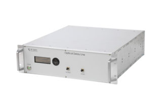
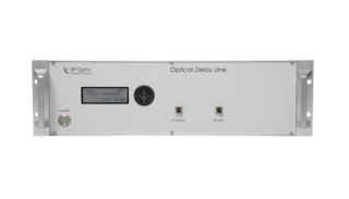
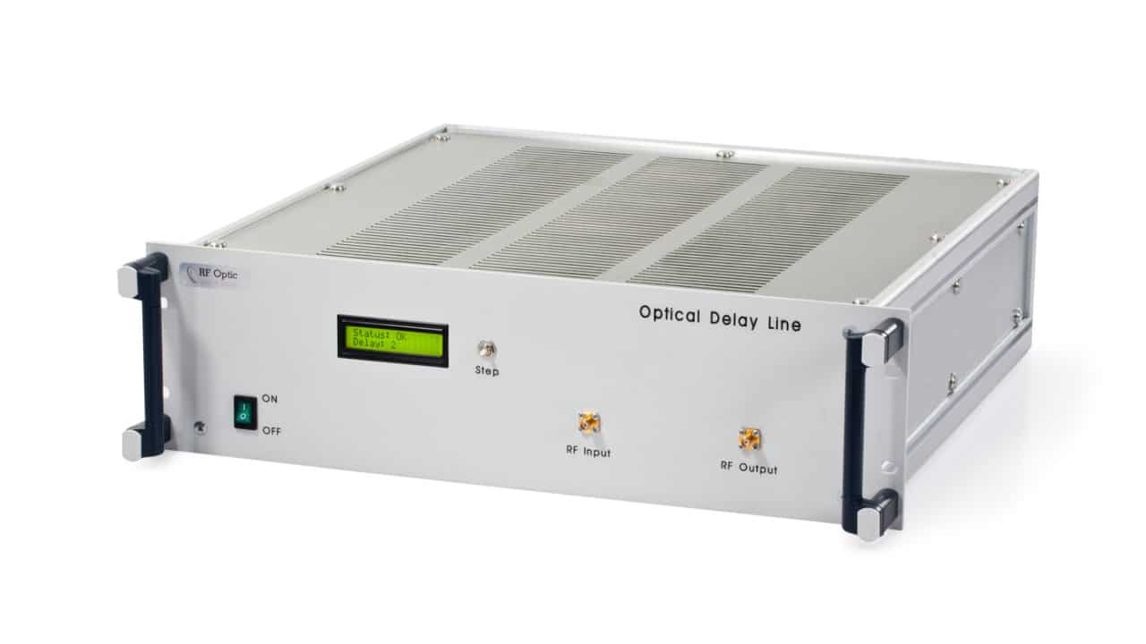
As mentioned in our latest newsletter, we have been very busy during Q1 of this year. Our R&D department has designed a new standard enclosure for our ODL solutions.
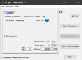
This new design features an informative display with a keypad that provides a clear readout of the ODL state and allows rapid manual adjustments. The manual controls are augmented with direct software control of all available features of the ODL. The management and control software is available through an USB interface with our standard RFOptic configuration tool, a special application that is dedicated to provide GUI to all RFOptic products including RFoF programmable links, RFoF HF series links, and ODL systems. By using an LCD and a 3-button navigation pad, it is now possible to control the system without any additional computer.
The new Optical Delay Line design supports a large set of features and custom options, including: Fixed and progressive delay configurations with 256 states or more with bandwidth up to 40GHz, and high-speed delay switching under 100μsec. Other features, such as RF and optical routing, amplification, and attenuation are available upon request. Currently, our optical delay lines are managed locally through the USB port or managed and controlled with our optical delay lines via our HTML/SNMP management system.
In general, we offer four groups of ODLs:
Any type of fixed or progressive ODL of up to 6.0GHz with direct modulation (L, S, & C bands).
Any type of fixed or progressive ODL of up to 8.0GHz – 18GHz with indirect modulation (L, S, C, X, & Ku bands).
Any type of fixed or progressive ODL of up to 20GHz, up to 27GHz and up to 40GHz upon request.
Altimeter Optical Delay Line(ALT ODL), providing a high-performance solution for testing and calibration of radar altimeter systems.
To meet the need of customers, we have launched our high-frequency Altimeter Optical Delay Line (ALT ODL) to provide a high-performance solution for testing and calibration of radar altimeter systems. The ALT ODL is part of the RFOptic’s family of Optical Delay lines.
RFOptic’s ALT ODL unit is a compact solution, which provides superb signal performance and altitude simulation accuracy with an ultra-silent operation.
The ALT ODL can be configured to emulate a single altitude or up to 4,096 altitude steps.
The Altimeter ODL offers very high accuracy up to 0.3ns for altitude steps under 6ft and > 0.1% above. The maximum altitude can reach 100,000 feet or 30Km in one enclosure.
An Optical Delay Line (ODL) is an electric-optic-electric instrument. It performs fixed time delay(s), between 0.01 and 250 μsec for RF signals up to 40GHz and more. The optical signal is transmitted into a long single-mode fiber, usually at a 1.55 micron wavelength or similar. Passing through the fiber and a series of optical switches, the optical signal is converted back into an electrical RF signal. The electrical control on the ODL elects the optical system automatically, with no need for any tuning by the operator.
An ODL is required as a measurement tool to determine the signal distance from the target in Radar systems. Since the speed of light in the fiber is slowed down by the fiber (index of reflection), 100 μsec equals about 20 km. Since the propagation of the light is equal for all RF frequencies, an optical delay line is suitable for a wide range of frequencies, in contrast to a coax delay line.
In general, there are three types of Optical Delay Lines:
Any type of fixed or progressive ODL up to 6.0GHz with direct modulation (L, S, & C bands)
Any type of fixed or progressive ODL up to 8.0GHz – 18GHz with indirect modulation (L, S, C, X, & Ku bands).
For some radar calibration & testing, signal & phase noise processing, and extension of radar range site applications, a Mini ODL in a ruggedized enclosure is required, available up to 6 GHz with direct modulation, and from 6 GHz up to 18 GHz with indirect modulation.
When hundreds of delay combinations are needed, variable ODL is required, which supports up to 12 distinct delay lines.
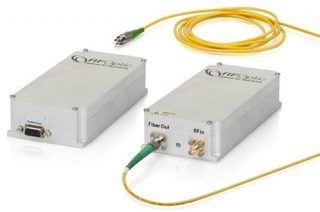
An Optical Delay Lines system (ODL) also incorporates high-performance lasers such as DFBs, optical modulators for high operation frequencies, photodiodes, and optionally other components such as optical dispersion compensators, optical switches, optical amplifiers, and pre- and post RF amplifiers to provide exceptionally high performance. The ODL optical system supports very high bandwidths of analog signals, high sensitivity with wide dynamic range, for various delays.
ODL solutions consist of the following components:
Optical amplifiers (to amplify the optical data signal without changing it into its electrical form)
RF amplifiers (to amplify a low power RF signal to one with a larger amplitude)
Dispersion compensators (to compensate for loss due to dispersion)
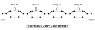
The most common practical approach for a variable delay system is an ODL system configuration, which includes cascaded 1:2 and 2:2 optical matrices with several different delay lines in between (replacing the above two optical switch matrix 1:8). This cascaded switch matrix is a Progressive Delay Configuration, as shown below.
The desired combination of delay lines is selected to define the required delay. In the diagram below, there are 4 progressive delay lines with cascaded switch matrices. In such a configuration, the user can select any of the 16 combinations of possible delay values (16=24). For example, a delay can be selected which is equivalent to Dtot= D1+D2 +D4, or Dtot= D3+D4, etc.)
Progressive Optical Delay Line configuration consisting of four 2:2 optical switch, providing 16 different delay lengths.
Sometimes, dispersion compensation is needed when the signal frequency and the delay line length increase, resulting in the optical signal to be dispersed and weakened significantly. As RFOptic, we solve this problem by incorporating DCM (Dispersion Compensation Module) in our Optical Delay Line (ODL) solutions.
For very long delay lines, RFOptic also uses Optical Amplifiers (EDFAS) to compensate for the optical loss. In some cases, also Pre and Post amplifiers are required.
Any changes of the delay lines and the attenuation are made through a user-friendly software interface with easy to use GUI (Graphic User Interface).
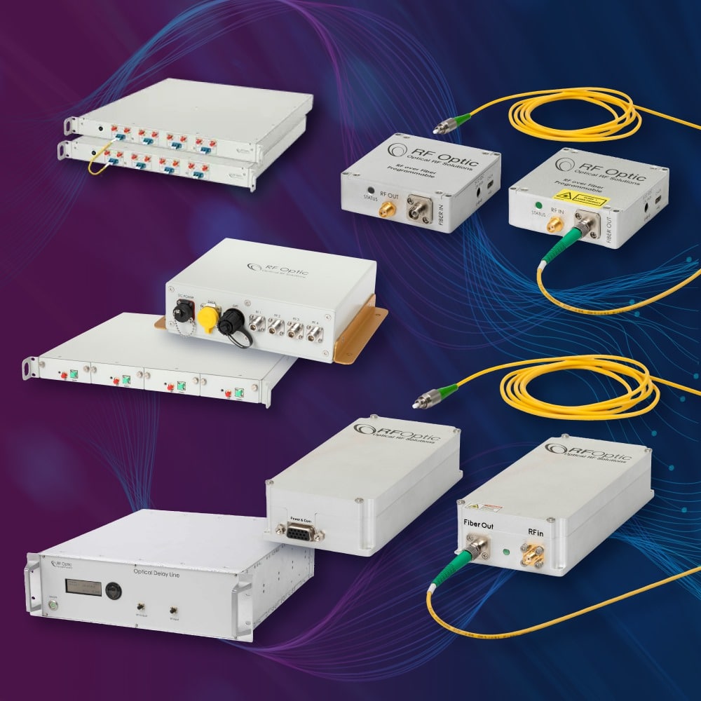
RFOptic is a leading provider and vendor of RF over Fiber (RFoF) and Optical Delay Line (ODL) solutions as well as embedded RF Optical solutions for OEM customers in the telecommunications, aerospace & defense, broadcasting, and infrastructure industries.
RFOptic is known for its RFoF links, multi-link / multi-channel RFoF systems and subsystems to meet customer requirements, including diverse enclosures (indoor and outdoor), and supporting multiple RFoF links with monitoring and management capabilities. RFOptic’s RF over Fiber solutions offer the best cost performance ratio, featuring noise figure of 5dB and gain link of around 40dB.
The programmable low frequency RF over Fiber units (0.5MHz to 6GHz) are based on direct modulation. The MiniQ High SFDR series indirect modulation product family supports applications from 10MHz to 40GHz with low noise and high spurious-free dynamic range (SFDR). RFOptic’s Optical Delay Line solutions are available as “fixed” ODL with up to 8 predefined time delay values in a single unit, or as “variable” supporting up to 255 delay states. All Optical Delay Lines feature delays of up to 250 μsec (>250 μsec upon request) while maintaining excellent performance. Customers can add RFoF functionality with RFOptic’s compact OEM board for high volume requests. The company’s unique software communicates with our programmable RFoF units, offering you unparalleled flexibility for you RFoF or ODL deployments.
In addition, RFOptic also develops, integrates, and delivers the most cost-effective and state-of-the-art product development of mixed microwave and optical solutions to companies worldwide. The company’s extensive experience and know-how overcomes the technological challenges which customers face, from original concept up to production.
The procedure for customized solution consists of 5 steps from request to implementation:
Getting the requirements from the customer
Building the concept
Defining the specifications and setting the budget
The tender was issues by he South African Radio Astronomy Observatory (SARAO) for the supply of broadband 18 GHz fiber optic links to be deployed at its Hartebeesthoek Radio Astronomy Observatory (HartRAO) site. It was to be used on HartRAO’s new Very Long Baseline Interferometry Global Observing System (VGOS) radio telescope.
Accutronics offered with its tender submission the 18 GHz HSFDR (High Spurious Free Dynamic Range) links manufactured by RFOptic. HartRAO required an Antenna Remoting solution that allows for the transmission of RF signals with a frequency range from 1 to 18 GHz over fiber while maintaining low spurious levels and excellent linearity. As RFOptic’s distributor in the region and with a solution that exceeds the requirement specifications, the logical choice was to offer the 18GHz HSFDR solution from RFOptic.
A high spurious-free dynamic range (SFDR) is desirable when multiple signals of very different power levels are expected to coexist. The high SFDR RFoF solution simplifies signal conditioning requirements that are required to avoid signal saturation and related complications including ALC and power range switching with attenuators or gain blocks.
Winning this important tender together together with Accutronics is a major achievement for RFOptic. It underlines the professionalism of Accutronics and the technology of RFOptic. The company’s high spurious-free dynamic range (SFDR) solution provides the best cost performance, has a high SFDR of 113 dB/Hz and a spurious level of less than -95dBm. Additionally, it offers excellent phase noise, phase linearity, and gain flatness. It can also be supplied in a variety of indoor and outdoor enclosures, thus offering great versatility.


 RFOptic