GPS signals have to be transferred from the antenna to a control room in mobile networks architecture. Sometimes, the physical distances are more than a few kilometers which preclude the use of coax cable due to high loss. Minimal fiber infrastructure drives mobile companies to use the same infrastructure for GPS and digital signals using WDM technologies.
The GPSoF solution of RFOptic allows signals to be carried from an antenna to a GPS receiver over fiber with minimal signal degradation. The GPSoF connection operates at low signal levels, e.g., directly from the antenna to the network in case of GPS. The Tx unit uses an optical transmitter to convert RF to Optical signal. The Rx unit converts it back to RF signal. The two units are connected through the customer’s single mode fiber.
The RFoF links are designed to offer a low noise figure by integrating a built-in LNA in the transmitter and post amplifier in the receiver for these low level signals. A built-in bias-T is also available to power an additional front-end if necessary. The module is offered as RFoF in a compact aluminum case for indoor applications and in suitable outdoor enclosures.
The RFoF modules have a relatively high gain (about 40dB) with excellent gain flatness, and a low noise figure (thanks to the integrated LNA in the transmitter), and high SFDR. In addition, their power consumption is relatively low. The standard optical connector is FC/APC, with SC/APC being available upon request.
Key Features
Next generation RFoF modules with significant performances improvement.
Supports to 0.5 MHz – 2.5 GHz. (100MHz to 2.5GHz with standard Bias-T option)
Excellent linearity, excellent gain flatness, and Tx, Rx and link gain control.
Noise Figure better than 6 dB with LNA with MDS ~168 dB/Hz for very low incoming signals.
Internal micro-controller and optical monitoring and control enabled by software.
End-to-end diagnostics reduce installation and maintenance time, enabled by software.
Gain variation S21(fo) of ±1 dB for 90° C variation, utilizing special algorithm.
Since we at RFOptic get regularly questions about Optical Delay Lines, we have written this short article to answer the most frequent ones.
For starters, an Optical Delay Line system (ODL) incorporates high-performance lasers such as DFBs, optical modulators for high operation frequencies, and photodiodes. It can also incorporate other components such as optical dispersion compensators, optical switches, optical amplifiers and pre- and post RF amplifiers for exceptionally high performance. For various delays, the ODL optical system supports very high bandwidths of analog signals, high sensitivity with wide dynamic range.
The ODL method is so important, since it is the most accurate and reliable method for time domain measurement for delay times of a few nano seconds to hundreds of microseconds. In other words, an Optical Delay Line is a method of wave guide where the media is fiber with a fixed index of refraction and relative constant group delay variation.
There are various applications that can use ODL systems, such as radar range calibration, MTI (Moving Target Indication), clutter canceller, BIT, ground-based system test, radar warning receiver, jammers for EW systems, timing control, path delay simulation, and phase shift discriminator.
The Optical Delay line method is the most accurate and reliable method for time domain measurement for delay times of a few nano seconds to hundreds of microseconds. As mentioned above, an Optical Delay Line is a method of wave guide where the media is fiber with a fixed index of refraction and relative constant group delay variation. The main advantages of this method as compared to other methods are:
Delay Length – Long achievable delay line due to the extremely low loss of the fiber (~0.25dB/Km), which is not achieved in any other methods. There are methods that can measure a range of picoseconds such as light reflection but do not cover the typical range of radars or EW systems. There are also methods for very long delay lines in the order of milliseconds, which are not accurate for practical lengths of delays. Therefore, the Optical Delay Line is the suitable method for length range from a few nano seconds to hundreds of microseconds. Moreover, utilizing switching or progressive system architectures, it is possible to include several different delays in the same system, which saves space, weight etc.
Bandwidth – Optical Delay Line can support bandwidths from the MHz range to tenth of GHz. This allows for using the ODL in various applications which require high bandwidth, where other waveguide methods are limited in allowed bandwidth and applications. For example, SAW is used for a bandwidth of a few tenths of kilohertz.
Group Delay Variation – One of the most important issues for radar designers is that the delay will be equal in the entire bandwidth. Thanks to the fiber, the group delay is constant and very small compared to the delay length.
Spurious – The spurious level of the Optical Delay Line is small, supporting Doppler shift measurements / applications, where the noises which are caused due to the circuit boards are cleaned by the system.
Phase Noise – An important parameter in the performance of airborne radars is the phase noise of the radar’s carrier frequency. Low phase noise is important for an accurate long range detection of a target. Many phase noise testing sets utilize waveguide delay lines as part of the test circuit. Because of their size, weight, and signal attenuation, typical waveguide delay lines have length limitations. Replacing the waveguide with fiber optic delay line allows for a major reduction in size and weight, as well as an added ability to improve the sensitivity of the test set in measuring phase noise close to the radar’s carrier frequency. A laser diode with low Relative Intensity Noise (RIN) can provide at 0 delay length a phase noise less than -130 dBc (input of).
There are various applications that can use ODL systems, including:
Radar range calibration; MTI (moving target indication); Clutter Canceller; BIT; Ground Based System Test; Radar Warning Receiver; Jammers for EW Systems; Timing Control; Path Delay Simulation; and Phase Shift Discriminator.
The main features support transmission of RF and Microwave analogue signals, covering:
L, S, C, X, and Ku bands, for various applications.
Supports width bandwidth analogue signals.
Supports various delay lines ranging from a few ns up to hundreds of m
High dynamic range.
Excellent delay repeatability and phase linearity.
Small Group Delay Variation.
Easy operation – Manually or remotely through RS-232 or Ethernet.
Example of an Optical Delay Line Block Diagram
Main configurations:
Fixed Delay Line System
The basic ODL system configuration consists of one Transceiver and one fixed Delay Line module that are integrated in one enclosure. ODL versions where the Transceiver and Delay Line units are separated into two modules are optional. The two modules option provides the flexibility to use one ODL Transceiver unit with several passive Delay Line units. However, the ODL in one enclosure is more robust as the Delay Line fiber is fused to the system, while in the two modules configuration, there is a need of a connection between the two modules by at least two external fibers (for a single Delay Line) connected to the optical connectors on the two modules.
Variable Delay Line Systems
Variable Delay Lines are of considerable interest in a variety of Variable Delay Lines applications including radar range simulation and signal processing. There are two basic techniques to consider: Switched RF and Switched Fiber. Switched RF uses multiple Delay Lines and RF switches to select various delay values. This technique has a good performance, but is relatively expensive due to the multiple delay lines that are required. A second approach is of Switched Fiber Delay system which is more cost effective. It consists of an ODL system with includes several different Delay Lines, where two optical matrixes (e.g., 1:2, 1:4 or 1:8) select (either manually or through PC) the desired Delay Line (i.e. DL 1 to DL 8). The disadvantage of this approach is that the switches are relatively slow, with a switching time in the order of milliseconds.
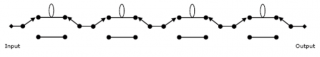
ODL Cascading System Configuration
This configuration includes cascaded 1:2 and 2:2 optical matrixes with several different delay lines in between (replacing the above two optical switch matrix 1:8). The cascaded switch matrix is shown below. It selects the desired combination of Delay Lines to define the desired delay. The image below shows a schematic representation of a four Progressive Delay Lines with cascaded switches matrixes. With such a configuration, the user can select any of the 16 combinations of possible delay values (16=24). For example, a Delay which is equivalent to Dtot= D1+D2 +D4, or Dtot= D3+D4.
Progressive Delay Configuration consisting of four 2:2 optical switched, providing 16 different delay lengths.
Recently, RFOptic attended two important industry events in Europe, namely the ECOC 2018 in Italy and the EuMW 2018 in Spain.
As a leading provider of RF over Fiber & Optical Delay Line solutions, both events gave us the opportunity to exchange views with follow industry leaders, meet our European distributors, and connect with current and potential customers as well as business partners.
The ECOC 2018 was held at the Fiera Roma in Italy. This European Exhibition on Optical Communications attracted over 6,500 executives and senior professionals from the industry’s largest and most influential companies around the globe to network, do business and learn. The exhibition hall itself was completely sold out, and featured 331 exhibiting companies from around the globe. The ECOC 2019, will take place in Dublin, Ireland.
The European Microwave Week (EuMW) 2018 took place in Madrid, Spain. In its 20th year, the event surpassed all records for delegate registration and exhibition size. Exhibitors included companies specializing in test & measurement, semiconductors, electronic design automation software, components, subsystems & systems, and special technologies. The EuMW 2019 will take place in Paris, France.
At both events, we introduces two of our latest offerings:
Our 26GHz for 5G cellular solution is a sub band of RFOptic’s RFoF 40Ghz product range. As with all our RFoF solutions, it features high SFDR and excellent flatness. It can be hosted as a standalone, indoor solution or outdoor solution.
Our SNMP/HTML interface to monitor, manage and control our products up to 6 GHz remotely. This new ability is especially suitable for applications such as broadcast, GPS, remote antenna, satcom, or any application where a group of modules is installed.
Attending industry events such as these are highly effective and we are looking forward attending more in the near future.
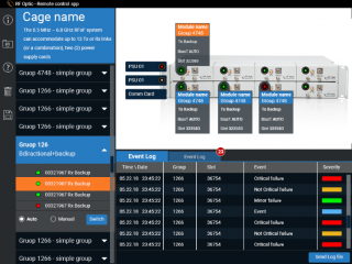
To meet the need of customers to manage their many units remotely, (e.g., in highway tunnels, satcom applications etc.) RFOptic has launched its SNMP/HTML capability. This enables system integrators, operators and control center staff to monitor and manage their RFOptic systems remotely. In other words, customers can not only control the system, but also monitor and change parameters remotely.
change all parameters, such as LNA (on / off) digital attenuation (at the Tx / Rx)
measure the optical and the RF power, reading all modules parameters.
Sending log files for investigation
Improved linearity and noise figure thanks to LNA and 31 dB attenuators in the Tx and the Rx enabling the customer to find the optimum working point with the specific fiber
Reduced Noise Figure down to 6 dB with LNA for very low incoming signals
An option to control the gain variation over temperature for 100 °C variation, utilizing special built-in algorithm
Optional Bias T in the Tx and the Rx
Allowing RF and Optical control (via the internal microcontroller)
Reducing installation and maintenance time (via end-to-end diagnostics)
The connection can be established in two modes:
Via the SNMP interface, where RFOptic will provide the MIB and traps that the customer can use in its own NoC system. In other words, the SNMP provides a set of commands and alerts that the customer integrated in his own system with his own propriety GUI.
Via a web browser, where the customer will receive a graphical description of the systems and modules utilizing the SNMP interface. This is an excellent option for smaller organizations that lack software support and therefore prefer an end-to-end solution including management & control.
The SNMP/HTML capability is suitable for RFOptic’s bidirectional, 1U generic, 1U removable units, as well as 2U removable units and all types of outdoors units. Any internal group that comprises even from one module can be supported. The customer can continue to support the modules locally as was done before.
Customers who are looking for life demo and would like to make a field trial are invited to contact RFOptic at sales@rfoptic.customcode.co.il
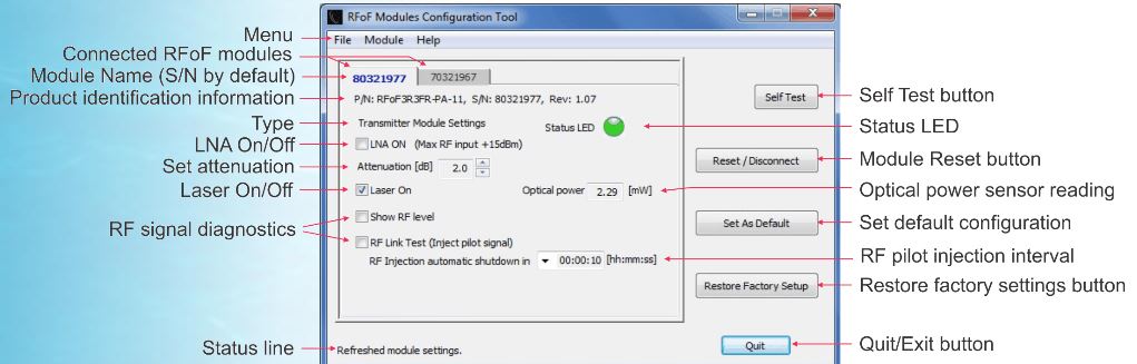
As RFOptic, we always strive to bring our customers of our RFoF and ODL solutions the best service and support in the field. That’s why we have developed unique software that allows you to configurate your RFOptic’s RFoF modules.
With the software, you can control one or more modules. All you need to do is to power up and connect your computer or tablet using a standard USB to interface with the software. Once connected, the software detects your RFoF modules, and you are ready to configurate and control them. The software is designed to work on PCs and laptops that run Windows 7, 8 or 10 operating system versions. Please note that it does not operate on previous operating system versions. However, a separate version for Windows XP. Is available. The software detects the modules automatically once connected.
Some of the features include:
Connecting Transmit (Tx) and Receive (Rx) RFOptic’s RFoF modules
Simultaneously connection to multiple modules
Obtaining status information and verifying the optical connection
Setting up and operating the configuration
Defining power-up default setup
Initiating self-test, RF module test and RF link test
With the software, it’s easy to check if your modules are connected correctly. (See also our video to learn more) The panel LED indicators on the RFoF modules will indicate if the optical fiber is connected or disconnected.
If the optical fiber is disconnected, the panel LED of the Tx is green and the panel LED of the Rx is red.
If the optical fiber is connected properly between Tx and Rx units, the panel LEDs of both Tx and Rx are green.
The image below illustrates the easy-to-use software offering a rich set of features and functionalities.
The software is made available free of charge under the license agreement, please make sure to familiarize yourself with the content before downloading and using the software.
Do you have any questions or remarks? Do you want to get more information? Feel free to contact us!


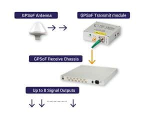 than a few kilometers which preclude the use of coax cable due to high loss. Minimal fiber infrastructure drives mobile companies to use the same infrastructure for GPS and digital signals using WDM technologies.
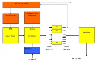

 As a leading provider of
 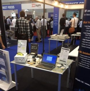 At both events, we introduces two of our latest offerings:
 To meet the need of customers to manage their many units remotely, (e.g., in highway tunnels,