Uncategorized

RFOptic has launched its innovative controllable phased-matched 6GHz RFoF modules

At RFOptic, we listen to our customers to provide solutions that they want and need. So when we got requests for programmable phased-matched 6GHz solutions, it was a no-brainer for us to have our R&D department working on it. (To download the brochure, click here)

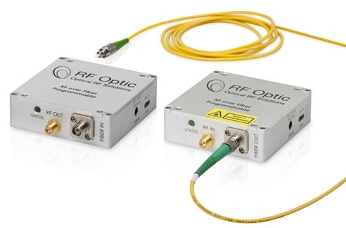
The palm-size analog RFoF modules are used to convert RF signals to optical signals to carry over long distances. The Tx unit using an optical transmitter, converts RF to Optical signal and the Rx unit converts back to the RF signal. The two units are connected through customer’s single-mode fiber.

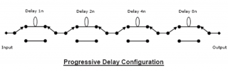
RFOptic’s RF over Fiber modules (RFoF) are suitable for Phased Array Radar, Electronic Warfare, and interferometry applications. RFOptic CWDM 6.0GHz RFoF 4 link system is phase-matched up to ±6˚ up to 5.7GHz. Each of the four links is comprised of a Tx unit with LNA and an Rx unit, both with variable attenuators that enable adjustment of the Noise Figure, Input P1dB, and IP3 over a wide range of values. The LNA can be activated through an RFoF software tool allowing RF input power in the range of -100 dBm/1MHz for wideband applications, with low Noise Figure of 6 dB. The RFoF link has excellent gain flatness with 0.5dB gain tracking between different links.

A user-friendly RFoF software enables adjustment of the RF and Optical parameters, such as link gain, Noise Figure, P1dB, Optical power, LED indication, and module information, either locally or remotely. In addition, the phased-matched 4 links DDM has HTML/SNMP interface so management and monitoring can be done remotely

Furthermore, the RFoF link has full diagnostic capability, including Tx, Rx and complete link test (Optical and RF). These features save cost of test equipment and provide real-time diagnostic of any deployed link. The link gain calculator helps to calculate the link gain and the optical predicted parameters for RFOptic’s programmable RFoF family.

Phased-Matched 6GHz RFoF Module Key Features:

  • Next generation RFoF system with significant performances improvement.
  • Supports up to 6.0GHz
  • Phased matched CWDM system of ±6 0 up to 5.7GHz
  • Gain matched 6.0GHz full band of ±2.5 dB
  • Better linearity, excellent gain flatness, and Tx, Rx and Link gain control
  • Noise Figure down to 6 dB with LNA with MDS ~168 dB/Hz for very low incoming signals
  • Internal Microcontroller allows RF and Optical control, enabled by software
  • End-to-end diagnostics reduces installation and maintenance time, enabled by software
  • Gain variation S21 (fo) of ±1 dB for 90° C variation, utilizing special algorithm
  • Remote management by GUI installed on PC
  • Impedances of 50 Ohms and 75 Ohm

To learn more, including the test results of the programmable 6.0 GHz RFoF phased matched system, download the datasheet or contact RFOptic at sales@rfoptic.customcode.co.il

Case Study – Airport Walkie Talkie Expansion

RFOptic’s programmable RF Over fiber links to connect about dozen radio systems to each other between the two terminals.

The Customer

Our customer is a systems engineering company specializing in airport communications.

The Challenge

The customer was working with a major airport based in the Northeast region of USA.  The airport was adding another terminal building and needed a solution for the employees of the airlines they are serving to communicate across the two terminals using their current Walkie Talkie 2-way radios.  Due to the long distance between the terminals our customer was considering using fiber.

The Solution

The customer chose RFOptic’s programmable RF Over fiber links to connect about dozen radio systems to each other between the two terminals.  RFOptic’s 1U chassis can house up to 4 transceivers.

There were multiple fiber patch panels between the two terminals.  As the radio systems needed a certain level RF input, the loss introduced by patch panels represented a challenge.  Further, some patch panels were in secure areas and not accessible by installers for inspection.

With ordinary regular RFoF systems the installers would have needed to add external amplifiers and attenuators to compensate for the patch panel losses to reach the required link budget.

Since RFOptic’s RFoF links have internal 30 dB LNA and 30 dB attenuators, the installers were easily able to modify the LNA and attenuator settings through the GUI to reach required system level link gains

The Result

Customer was able to quickly install and fine-tune the RF over Fiber links and expand the Walkie Talkie coverage to the new terminal.  A year later customer purchased additional RFoF links for additional radios.

What is an Optical Delay Line – ODL?

Understanding Optical Delay Lines: What is ODL?

An Optical Delay Line (ODL) is an electric-optic-electric instrument. (in some literature, an optical delay line is also referred to as fiber delay line or a fiber optic delay line),  It performs fixed time delay(s), between a few nanoseconds up to several hundred microseconds, for RF signals from 10MHz up to 40GHz and more. There are low-frequency ODL versions ranging from 10MHz to 6GHz. The high-frequency ODLs versions are up to 8GHz, 15GHz, 18GHz, 20GHz, and 40GHz.

On a more technical level, the RF input signal is converted into an optical modulated signal. The optical signal is transmitted into a long single mode fiber, usually at a 1.55 micron wavelength or similar. Passing the fiber, the optical signal is converted back into an electrical RF signal. The electrical control on the ODL elects the optical system automatically, with no need for any tuning by the operator.

Components and Features of Fiber Optic Delay Line

An Optical Delay Lines system (ODL) also incorporates high performance lasers such as DFBs, optical modulators for high operation frequencies, photodiodes, and optionally other components such as optical dispersion compensators, optical switches, optical amplifiers and pre- and post RF amplifiers to provide exceptionally high performance. The ODL optical system supports very high bandwidths of analog signals, high sensitivity with wide dynamic range, for various delays.

Applications and Variable Optical Delay Lines

Variable Optical Delay Lines (also known as Progressive ODLs) are used in a variety of applications including radar range simulation and signal processing. The Progressive ODL has a few delay lines using the same transceiver where the customization is done by RFOptic.

The most common practical approach for a variable delay system is an ODL system configuration which includes cascaded 1:2 and 2:2 optical matrices with several different delay lines in between (replacing the above two optical switch matrix 1:8). This cascaded switch matrix is a Progressive Delay Configuration which is shown below.

Desired Combination of Delay Lines

The desired combination of delay lines is selected to define the required delay. In the diagram below, there are 4 progressive delay lines with cascaded switch matrices. In such a configuration, the user can select any of the 16 combinations of possible delay values (16=24). For example, a delay can be selected which is equivalent to Dtot= D1+D2 +D4, or Dtot= D3+D4 etc.)

Variable or Progressive Optical Delay Line Configuration Model

Progressive Optical Delay Line configuration consisting of four 2:2 optical switch, providing 16 different delay lengths.

Dispersion Compensation in Optical Delay Lines

Sometimes, dispersion compensation is needed when the signal frequency and the delay line length increase, resulting in the optical signal to be dispersed and weakened significantly. As RFOptic, we solve this problem by incorporating DCM (Dispersion Compensation Module) in our Optical Delay Line (ODL) solutions.

For very long delay lines, RFOptic also uses Optical Amplifiers (EDFAS) which compensate the optical loss. In some cases, also Pre and Post amplifiers are required.

Any changes of the delay lines and the attenuation are made through a user-friendly software interface with easy to use GUI (Graphic User Interface).

Contact Us for More ODL Information

For more information about Optical Delay Lines, contact us.

About RFOptic

RFOptic is a leading provider of RF over Fiber (RFoF) and Optical Delay Line (ODL) solutions. For the last 20 years, its team of industry veterans has been developing, designing and integrating superior quality technology for a wide range of RFoF and ODL solutions. The solutions are deployed at various industries, including broadcastingaviationelectronic warfare, and defense. RFOptic offers its customers and OEMs various off-the-shelf products, as well as custom-made solutions optimized for a wide range of RFoF products at affordable prices and with a quick turnaround. RFOptic makes it its mission to help its customers to turn innovation into real business by providing them with the highest quality, cutting edge RFoF solutions as well as customized solutions based on individual requests and objectives.