Optical Delay Line Applications
RFOptic’s Optical Delay Line (ODL) are lab instruments that enable radar production line test and calibration and have applications in RF communications. These products utilize low-loss optical fibers to provide true time delay. They are used to simulate signal delay for various types of radars including long range early warning, fire control, proximity fuse, intruder detection, altimeters and rangers. Our ODLs convert RF signals to optical signals, apply precise delays through segments of single-mode fiber and revert the signal to an RF output. ODLs are semi-custom products each configured to ensure signal fidelity and meet customer specifications of delay, gain and signal level values. Fixed delay are available and progressive delay models can be configured with up to 224 configurable delay combinations and delay range from 1ns to 500μs, extendable upon request. ODL’s are calibrated at production time and require no recalibration. They are offered with several delay switch speed options and support computer control for automation.
Trusted in Electronic Warfare and critical calibration applications, RFOptic’s Optical Delay Lines deliver performance and reliability. Choose RFOptic to enhance your systems with precision delay solutions enjoying efficient ODL definition and fast delivery.
Where and why use an Optical Delay Line?
Optical Delay Lines (ODLs) simulate precise true time delays for RF signals. They are compact instruments which enable lab or production line test and calibrate products which depend on signal timing for function such as radars. They maintain high signal integrity and precise time delays which are used to calibrate target distance. Compared to traditional electronic delay methods (digital or rolled coax cable), ODLs have advantages of wideband performance, flat response, low distortion and smaller size making them ideal for high-frequency applications. ODLs are an excellent choice for precise timing applications in telecommunications, radar, EW, and for scientific research.
Key Features
Optical Delay Lines (ODLs) offer a range of customizable features and options that enhance their performance and versatility in various applications. Standard ODLs occupy one or more 3U rack mountable enclosure(s) depending on the required delay segments. They feature a display and Navigation button for front panel control. The display can provide time delay, distance and altitude/range values to accommodate different applications. Fixed ODLS can be housed in a Mini-ODL enclosure or yet smaller OEM-ODL enclosure if their delay is short (under 32us and 20us respectively). All ODLs feature computer control interface which is either USB based (with free software app) for local control or network-based supporting Webserver as well as REST and SNMP V2c API’s. Fast delay switching ODLs have a direct TTL delay control to bypass network latency.
Common ODL Options
- High input RF level – Support for input signals up to 33dBm
- Pre and Post RF Amplifiers, optical amplifier(s) – Lower noise figure and/or increase output RF level
- Amplitude control – built-in or an added step attenuator
- RF switch – Output RF switch for on/off modulation
- Gain equalization – Compensates for variation in fiber loss at different delay states
- Delay expansion – Support customer’s external delay spool
RF Bypass – reduce insertion delay for calibration purposes - Optical Bypass – reduces the Zero State Delay for ODLs with large number of delay segments
- Augmented Zero State Delay – Where possible, internal delay round up to the first delay step
- Fast delay switching – <100μs, or <1μs with direct TTL interface (std switch <10ms)
- Bidirectional ODL – 2-way signal transmission
- Doppler Modulation – Adds a relative speed simulation to the ODL output signal
- DC Power – Used for OEM integrated ODLs
Coverage & Frequencies
Optical Delay Lines (ODLs) are available for a wide frequency bands from 1MHz up to 67GHz, making them versatile for various applications in altimeter, telecommunications and radar systems. They can be designed to operate across all common frequency bands, including L band, S band, C band, X band, Ku band, K band, Ka band, V band, and beyond. This broad frequency coverage allows ODLs to accommodate diverse signal types and applications, from long-distance communication to high-resolution radar imaging.
System Configuration (Example)
The Optical Delay Line (ODL) system is engineered to provide precise time delays for RF signals through a combination of optical fiber delay segments and other components. Central to the system are RFoF transceivers, which convert incoming RF signals into optical signals and surround the delay segment(s) on both ends. In progressive ODLs the fiber delay segments are connected to a switch array that engages fiber segments as required to achieve the required delay. A typical ODL would have 8 delay segments producing delays of 0.1μs, 0.2μs, 0.4μs, 0.8μs 1.6μs, 3.2μs, 6.4μs and 12.8μs. Such ODL would have a typical internal delay of 56ns. In such case the achievable delay series would be: 0.056μs, 0.156μs, 0.256μs, 0.356μs … up to 25.556μs. If an Augmented Zero Delay State is opted for, then an additional delay segment (of 0.044μs) would be used to round the Zero State Delay to the minimum delay step value of 0.1μs. The ODL then would deliver the following delay values series: 0.1μs, 0.2μs, 0.3μs, … up to 24.6μs.
Main applications
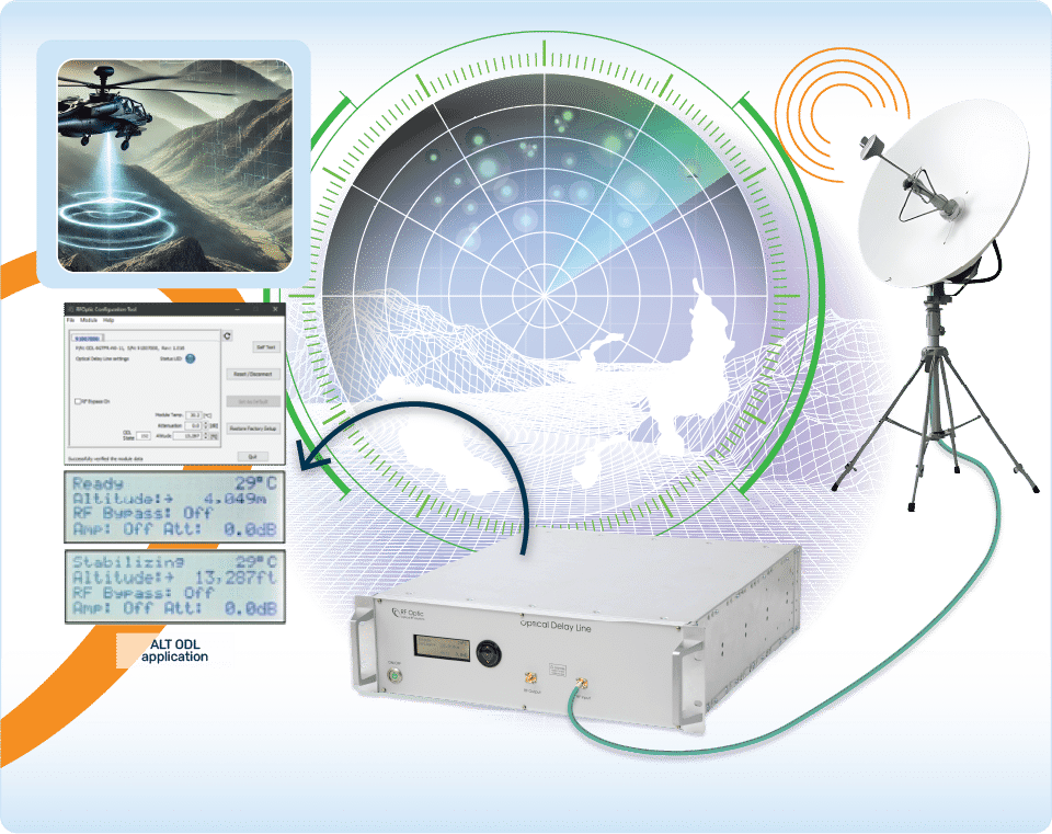
ODLs are indispensable for radar test and calibration as they enable simulation of open range target distances in a lab or at the production line. Any other system that needs to sense or respond to delayed signals can benefit as well since ODLs can be used to simulate fading effects, multi-path and multi-target EW simulators. In some cases, usually fixed delay ODLs are integrated into EW systems to allow off line identification and tracking of input signals while the original signal, usually pulsed RF, is still stored in the ODL path and can be processed afterwards. The analog characteristic of ODLs ensures that neither the EW signal amplitude profile nor its frequency content are tampered with. ODLs provide altitude and range standard in altimeter and ranger test.
Monitoring & Control
The Optical Delay Line (ODL) system features robust monitoring and control capabilities for efficient operation. The standard USB interface is available with a free software app. Alternatively a network-based interface is available as well using IP to provide Webserver, REST API and SNMP V2c access to the controls of the ODL
Conclusion
Optical Delay Lines are important instruments that provide precise true time delay. They are particularly useful for radar and altimeter calibration and for exercising such systems that measure distance using reflected radio waves. These systems have configurable time delay (equivalent to distance, altitude or range) values and resolution. ODLs are available with a multitude of signal conditioning and modulation options with computer control API that is suitable for automated testing.
Request for Quote