Radar

RFOptic’s progress in Asia

RF over Fiber & Optical Delay Line Solutions From RFOpticIn general, some Asia Pacific countries, led by China, India, Japan, and South Korea, are investing considerably in homeland security and defense applications. For the last few years, RFOptic has made significant progress in various markets in Asia. Based on our commercial success, we are looking forward to accelerating our growth across several key Asian markets this year. We will expand our footprint in the local EW & Defense and 5G testing sectors thanks to the increasing demand for advanced optical RF solutions. Let’s have a closer look at our progress in more detail, focusing on Japan, India, Vietnam, China, and South Korea.

Japan: A Promising Future
The Japanese market is experiencing robust growth, particularly in applications such as telemetry, remote antennas, and 5G technology. Thanks to the commitment and efforts of our local distributor, Fuchu, we have entered the Japanese market successfully. Following our success in the last few years, we anticipate tripling our local sales this year, mainly through repeat orders. We expect our recently launched Ultra 12GHz and 18GHz products to drive local demand.

To learn more about our Ultra 12GHz product solution, click here. To learn more about our Ultra 18GHz product solution, click here.

India: Strategic Partnerships and Expanding Projects
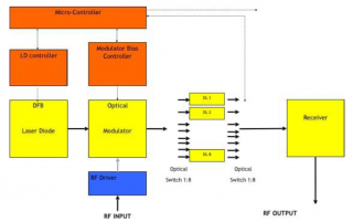
Following successful trials of our 6GHz phase-matched point-to-point and 18GHz four-channel demonstrations, RFOptic has been awarded two major projects. The first one is with the Defense Research and Development Organisation (DRDO). The second one consists of our optical RF solutions at millimeter wavelengths for maritime applications. To get a permanent foothold in this strategic market, we have been building cooperations with first and second-tier integrators. These strategic relationships allow us to provide e.g., our Government & Defense solutions to meet the growing demand from the defense sector.

To learn more about our customized RF over Fiber high SFDR for 5G mm-Wave active antenna arrays, contact us.

Vietnam: New Opportunities
As we mentioned in our previous blog post, Vietnam is emerging as a major player in the EW & Defense sector, also thanks to strong players such as the Viettel Group. There is especially a strong demand for optical delay lines and systems for RADAR altimeter testing. This was also evident at a recent exhibition where we were represented by our local partner s9 Technology JSC. Also, based on the success of this expo, we expect significant market growth as the demand for our innovative solutions, such as for our phase-matched CWDM multi-link RFoF, continues to rise.

To learn more about our Optical RF Electronic Warfare & Radar Systems, click here.

China: Continued Success and Repeat Orders
As RFOptic, we are also active in China. Our success record includes receiving a third consecutive order from the Radio Telescope Observatory in Shanghai. We supplied advanced 18GHz and 6GHz links, alongside our HTML management system. Our solutions for remote antenna applications in electromagnetic compatibility (EMC) have also resulted in repeat orders. With the launch or our Ultra product line, which is known for its compactness, lightweight design, and performance, we expect continued growth in this market. Other deployments include South African Radio Astronomy Observatory (SARAO) for the supply of broadband 18 GHz fiber optic links for its Hartebeesthoek Radio Astronomy Observatory (HartRAO) site, and the Onsala Space Observatory.

For more information about our RFOptic’s fiber optic solutions for Radio Telescope and Astronomy, click here.

Korea: A Key Market
Another rapidly growing market for us at RFOptic is South Korea. The main demand is for our optical delay lines and HSFDR product lines for defense and DAS applications. Due to the changing geo-political situation, we forecast a growing need for our off-the-shelf and customized solutions. Therefore, we consider South Korea, being an essential market, to play a crucial part in our overall growth strategy in Asia.

To learn more about our DAS solution, click here.

Other Markets: Significant CAGR Growth
The overall demand for RFOptic’s products highlights a strong compound annual growth rate (CAGR) across the Asian market, outpacing the global average. Our track record of providing creative, compact solutions and excellent support makes us the preferred choice. This positions us well to provide our 5G RFoF subsystems and Electronic Warfare & RADAR solutions in these important markets.

In conclusion, as RFOptic, we are looking forward to strengthening our presence in these dynamic markets even more. As always, our main focus will remain on developing and providing innovative solutions that meet our customers’ needs.

The importance of RFOptic’s presence at the Tyndall Air Force Base Tech Expo 2024

On December 10, 2024, we, as RFOptic, co-exhibited at the Tyndall Air Force Base Tech Expo together with Southern Marketing Associates (SMA, Inc.). Hosted by the 325th Communications Squadron, the event took place in Panama City, FL. After setting up our booth early, we were ready to meet captains, majors, other officers, and members from EW and engineering wings during their walkabout.

We were invited to deliver a speech to the Tyndall AFB leadership presenting RFOptic and explaining about our mission, solutions, and, in general what we do and stand for. We introduced our three RFoF product lines (0.5MHz to 6GHz RFoF programmable, 0.1GHz up to 67GHz HSFDR RFoF, and ODL and Altimeter ODL) as well as our custom solutions, such as DF/Phase match, optical mixer, phase control, and HD systems. It was received well and resulted in several officers visiting us directly afterward.

From those meetings, it is clear that their main interest is in remote antenna and simulator applications. Our RF over Fiber high SFDR for satellite remote antenna applications consist of outdoor and indoor end-to-end solutions up to 40GHz are suitable for Ku and Ka satellite antennas. The indoor terminal can be installed up to several kilometers from the outdoor solution that can be controlled remotely. This especially useful if a LAN connection near the antenna is impossible.

Our Altimeter RADAR Test solution is a high-frequency Altimeter Optical Delay Line (ALT ODL) solution for testing and calibration of radar altimeter systems. Benefits include very high accuracy and a maximum altitude of 100,000 feet or 30 km in one enclosure.

The Tyndall AFB Tech Expo aims to foster innovation, collaboration, and education by bringing together government and industry to address mission requirements and technology solutions to address mission requirements and technology solutions. What made this event unique, was that all organizations, units, and tenant commands were invited to explore, assess, and learn about current and upcoming technologies.

  • Innovation helps Tyndall AFB personnel to stay current on industry trends, evaluate the latest emerging technologies related to its mission, and explore innovative solutions to current challenges.
  • Collaboration consists of connecting Tyndall AFB personnel with industry partners (such as RFOptic), meeting new solutions providers, and discovering ways to adapt new technologies into existing infrastructures.
  • Education focuses on sharing knowledge on future requirements, learning about enhancements to current products and services, and supporting industry outreach.

It was an excellent opportunity for Tyndall AFB personnel to identify potential solutions and products worth exploring further. In general, we talked to many potential customers who showed a specific interest in our offerings.

To learn more, contact us.

Our participation in IMS2024 was a great success!

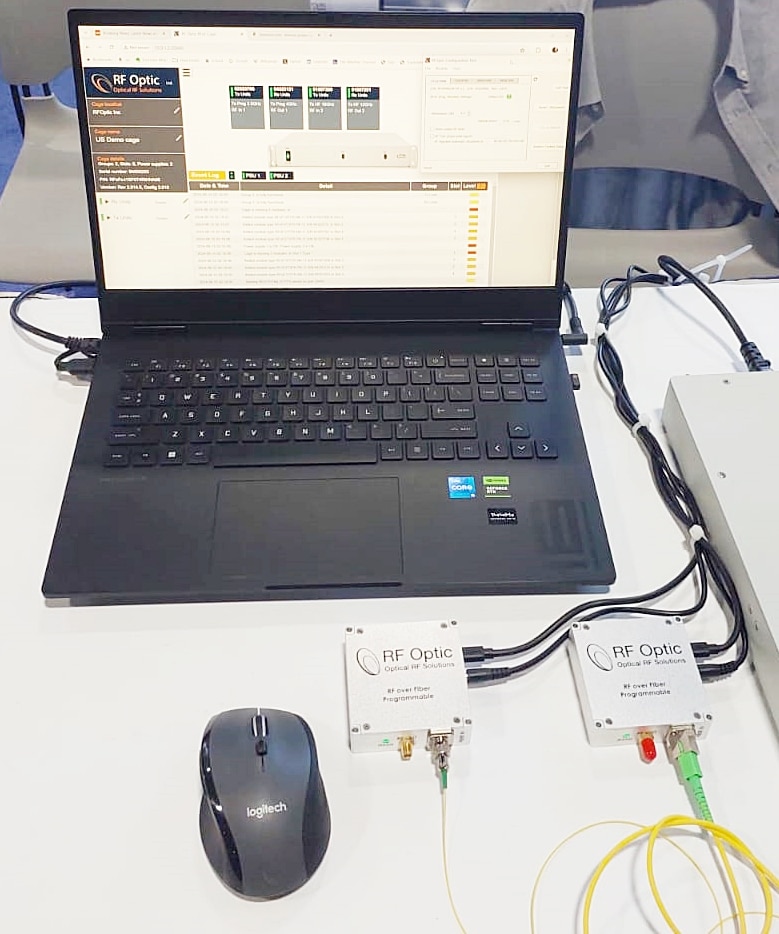
In June, we participated for the first time in IMS2024. The IEEE MTT-S International Microwave Symposium is a yearly event. This year, it took place in the Walter E. Washington Convention Center in Washington, DC, offering exhibitors a chance to connect with 9,000+ members of the RF and Microwave community from across the globe.

At our booth, we showcased our RFoF & ODL solutions for Electronic Warfare & Radar, 5G testing, and DAS applications, attracting many visitors. We received visitors from all over the world representing government agencies, major system integrators, and commercial enterprises active in the 5G cellular, satcom, broadcast, government & defense, testing & measuring, and Electronic Warfare & Radar industries.

We talked to more than 100 visitors who left their details to be contacted after the show, which resulted in sending out several proposals for RFoF solutions.

Our live demo got a lot of attention from interested parties, who asked our experts detailed questions.

The show also gave us a good opportunity to meet some of our distributors to catch up. We had meetings with representatives from Municom GmbH, our distributor for Central Europe, Fusoh Shoji Co., Ltd. from Japan, Amtele Communication, our distributor for Scandinavia, Matech from France, and Mitron from China.

The show demonstrated that there is a growing demand for the type of RF over Fiber subsystems and solutions that we, as RFOptic, offer.

Our next participation in an international exhibition will be at the upcoming European Microwave Exhibition. EuMW 2024 will take place during September 24-26 in the Paris Convention Center, 1 place de la Porte de Versailles 75015 Paris. At the event, we will co-exhibit in booth 422b of the company MATECH. We will showcase our advanced solutions for RFoF & ODL solutions for Electronic Warfare & Radar5G testing, and DAS applications. If you are interested in setting up an appointment with our VP Mr. Oz Abramson, during the event, click here.

RFOptic has launched its high frequency links with ultra-low spurious level for RADAR and EW applications

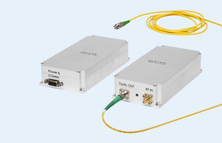
At the request of customers, RFOptic has now launched 12GHz, 18GHz, 20GHz, 30GHz, and 40GHz RF over Fiber links that have an ultra-low spurious level of less than -95dBm. This means that RFOptic’s MiniQ RFoF series provide spurious-free dynamic range (SFDR) better than -112dB/Hz. Spurious RFoF solutions are essential in order to mix non-harmonic spurious signals with the input RF signals at the output of the RFoF link. The spurious signals increase the Probability of False Alarm (PFA) and Minimum Detection Signal level (MDS) for EW and RADAR systems and degrade the Adjacent Channel Power Ratio (ACPR) in communication systems.

On a technical level, achieving extremely low spurious levels is a major challenge, particularly in small and tight RFoF modules where power consumption must be kept as low as possible. Many applications can only be supported by a design that achieves low spurious levels across extremes of the RFoF link bandwidth. Applications such as Optical Delay Lines, used in many RADAR test ranges, require ultra-low spurious to test and optimize extremely sensitive systems.

Thanks to the efforts of RFOptic’s R&D department, the new offering will achieve this critical parameter, which opens the market for RADAR and EW as well as other applications.

In general, a high spurious-free dynamic range (SFDR) is desirable when multiple signals of very different power levels are expected to coexist. A high SFDR RFoF solution simplifies signal conditioning requirements that are required to separate true signals from the unwanted spurious. There are well-known techniques, which are intended to identify the spurious signals and null them including LO dither, adjustable ALC, and power range stepping.

However, these techniques complicate the extraction of the real signals of interest and require extra signal processing, which now can be reduced or re-directed to deal with the real input signals rather than with artifacts of the RFoF link. During antenna, RADAR, or communications system testing, high SFDR is essential due to the typical large signal amplitude ratios between main and side lobes or between close and distant targets. The same applies to DF/ELINT systems, which have to handle strong jammers concurrent with weak signals of interest.

To learn more, click here or contact RFOptic at sales@rfoptic.customcode.co.il.

Everything you always wanted to know about Optical Delay Lines

Since we at RFOptic get regularly questions about Optical Delay Lines, we have written this short article to answer the most frequent ones.

For starters, an Optical Delay Line system (ODL) incorporates high-performance lasers such as DFBs, optical modulators for high operation frequencies, and photodiodes. It can also incorporate other components such as optical dispersion compensators, optical switches, optical amplifiers and pre- and post RF amplifiers for exceptionally high performance. For various delays, the ODL optical system supports very high bandwidths of analog signals, high sensitivity with wide dynamic range.

The ODL method is so important, since it is the most accurate and reliable method for time domain measurement for delay times of a few nano seconds to hundreds of microseconds. In other words, an Optical Delay Line is a method of wave guide where the media is fiber with a fixed index of refraction and relative constant group delay variation.

There are various applications that can use ODL systems, such as radar range calibration, MTI (Moving Target Indication), clutter canceller, BIT, ground-based system test, radar warning receiver, jammers for EW systems, timing control, path delay simulation, and phase shift discriminator.

The Optical Delay line method is the most accurate and reliable method for time domain measurement for delay times of a few nano seconds to hundreds of microseconds. As mentioned above, an Optical Delay Line is a method of wave guide where the media is fiber with a fixed index of refraction and relative constant group delay variation. The main advantages of this method as compared to other methods are:

  • Delay Length – Long achievable delay line due to the extremely low loss of the fiber (~0.25dB/Km), which is not achieved in any other methods. There are methods that can measure a range of picoseconds such as light reflection but do not cover the typical range of radars or EW systems. There are also methods for very long delay lines in the order of milliseconds, which are not accurate for practical lengths of delays. Therefore, the Optical Delay Line is the suitable method for length range from a few nano seconds to hundreds of microseconds. Moreover, utilizing switching or progressive system architectures, it is possible to include several different delays in the same system, which saves space, weight etc.
  • Bandwidth – Optical Delay Line can support bandwidths from the MHz range to tenth of GHz. This allows for using the ODL in various applications which require high bandwidth, where other waveguide methods are limited in allowed bandwidth and applications. For example, SAW is used for a bandwidth of a few tenths of kilohertz.
  • Group Delay Variation – One of the most important issues for radar designers is that the delay will be equal in the entire bandwidth. Thanks to the fiber, the group delay is constant and very small compared to the delay length.
  • Spurious – The spurious level of the Optical Delay Line is small, supporting Doppler shift measurements / applications, where the noises which are caused due to the circuit boards are cleaned by the system.
  • Phase Noise – An important parameter in the performance of airborne radars is the phase noise of the radar’s carrier frequency. Low phase noise is important for an accurate long range detection of a target. Many phase noise testing sets utilize waveguide delay lines as part of the test circuit. Because of their size, weight, and signal attenuation, typical waveguide delay lines have length limitations. Replacing the waveguide with fiber optic delay line allows for a major reduction in size and weight, as well as an added ability to improve the sensitivity of the test set in measuring phase noise close to the radar’s carrier frequency. A laser diode with low Relative Intensity Noise (RIN) can provide at 0 delay length a phase noise less than -130 dBc (input of).

There are various applications that can use ODL systems, including:

  • Radar range calibration; MTI (moving target indication); Clutter Canceller; BIT; Ground Based System Test; Radar Warning Receiver; Jammers for EW Systems; Timing Control; Path Delay Simulation; and Phase Shift Discriminator.

The main features support transmission of RF and Microwave analogue signals, covering:

  • L, S, C, X, and Ku bands, for various applications.
  • Supports width bandwidth analogue signals.
  • Supports various delay lines ranging from a few ns up to hundreds of m
  • High dynamic range.
  • Excellent delay repeatability and phase linearity.
  • Small Group Delay Variation.
  • Easy operation – Manually or remotely through RS-232 or Ethernet.

Example of an Optical Delay Line Block Diagram

Main configurations:

  1. Fixed Delay Line System

The basic ODL system configuration consists of one Transceiver and one fixed Delay Line module that are integrated in one enclosure. ODL versions where the Transceiver and Delay Line units are separated into two modules are optional. The two modules option provides the flexibility to use one ODL Transceiver unit with several passive Delay Line units. However, the ODL in one enclosure is more robust as the Delay Line fiber is fused to the system, while in the two modules configuration, there is a need of a connection between the two modules by at least two external fibers (for a single Delay Line) connected to the optical connectors on the two modules.

  1. Variable Delay Line Systems

Variable Delay Lines are of considerable interest in a variety of Variable Delay Lines applications including radar range simulation and signal processing. There are two basic techniques to consider: Switched RF and Switched Fiber. Switched RF uses multiple Delay Lines and RF switches to select various delay values. This technique has a good performance, but is relatively expensive due to the multiple delay lines that are required. A second approach is of Switched Fiber Delay system which is more cost effective. It consists of an ODL system with includes several different Delay Lines, where two optical matrixes (e.g., 1:2, 1:4 or 1:8) select (either manually or through PC) the desired Delay Line (i.e. DL 1 to DL 8). The disadvantage of this approach is that the switches are relatively slow, with a switching time in the order of milliseconds.

  1. ODL Cascading System Configuration

This configuration includes cascaded 1:2 and 2:2 optical matrixes with several different delay lines in between (replacing the above two optical switch matrix 1:8). The cascaded switch matrix is shown below. It selects the desired combination of Delay Lines to define the desired delay. The image below shows a schematic representation of a four Progressive Delay Lines with cascaded switches matrixes. With such a configuration, the user can select any of the 16 combinations of possible delay values (16=24). For example, a Delay which is equivalent to Dtot= D1+D2 +D4, or Dtot= D3+D4.

Progressive Delay Configuration consisting of four 2:2 optical switched, providing 16 different delay lengths.

To learn more, contact, sales@rfoptic.customcode.co.il or visit rfoptic.customcode.co.il